These are my notes on the Cessna 182 RTF from Hobby King.
I had to replace the XT60 connectors on the charger and battery with Deans connectors to suit the plane. According to the guy at Hobby Habit XT60 is mainly a US thing. I also replaced the alligator clips on the charger input with a molex connector so I can power it from my PC.
The manual is not much use as it's missing several vital details (for a novice anyway).

 -- DanielOConnor - 22 Jun 2011
- The ESC powers the receiver directly, not with a separate cable, so it plugs only into channel 3. The battery port on the receiver is used with the bind plug to rebind to the transmitter.
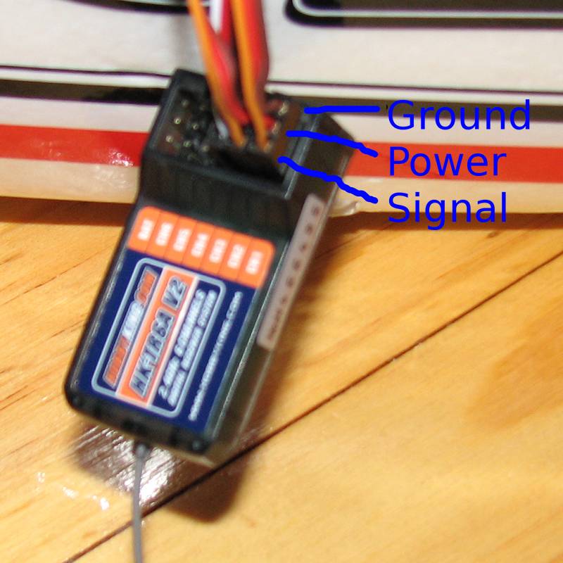
- The receiver & servo pinouts are undocumented, see the following table & attached image.
- There was not much glue and it smelt like PVA so I used some of that.
- The receiver is quite programmable using the USB cable ($3 from HK) using this software ($2).
- By default switch A selects between single (toward you) & double (away) rate and switch B kills the throttle (towards you = no throttle).
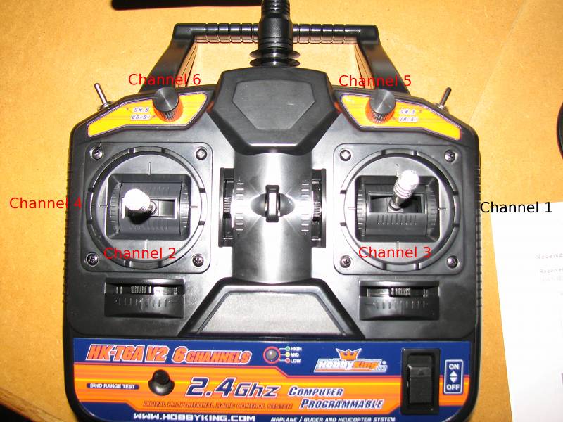
- The transmitter channel assignment is shown in the picture, all of the sticks have centre springs except for channel 3.
- ESC "manual" (Skyartec BMC-25A)
- I got a Turnigy ESC programming card on the assumption the plane had a Turnigy ESC but it has Skyartec, card seems to work OK though.
- The motor is a Skyartec WZ12 Outrunner 1530KV which has a shaft size of 3mm.
- The propeller is 8x6 and needs a small hub (10mm) for the spinner to fit on
- The curvy side of the prop should face forward (typically this means the writing should face forward).
- The first time you use the ESC you have to set the throttle range, check the ESC manual (search for "throttle range setting")
Technical
- The receiver has what I think is an Amiccom A7105
- There is also a 24C02B which should be a 256byte I2C EEPROM, although I can't determine the maker (probably .cn cloner).
- There is a mystery chip which drives the PWM outputs, not sure what it is yet, hopefully a CD4017 so I can MitM the PPM.
- Servo & PPM output signals are at 3.3V.
- The signal pin on the battery connector looks like a PPM output.
Simulation
- Install PPJoy (special pre-release version)
- Windows Vista and later need to be run in test signing mode for the PPJoy driver.
- I needed to reboot before the PPjoy joystick showed up
- Note it doesn't show up in Devices & Printers but you can run control /name Microsoft.GameControllers
- Get T6sim
- ClearView ($40) and FMS (free) seem to be the only sims which work with a Windows joystick.
Pictures
Wiring
| ESC | Servo | |
|---|---|---|
| Signal | White | Orange |
| Power | Red | Red |
| Ground | Black | Brown |
Channel assignment
| Channel | Function |
|---|---|
| 1 | Aileron |
| 2 | Elevator |
| 3 | Throttle |
| 4 | Rudder |
| 5 | Flaps |
| 6 | Unused |
| I | Attachment | Action | Size | Date | Who | Comment |
|---|---|---|---|---|---|---|
| |
RC-receiver.JPG | manage | 80 K | 22 Jun 2011 - 13:58 | Main.darius | |
| |
RC-transmitter.JPG | manage | 91 K | 22 Jun 2011 - 13:49 | Main.darius |
Edit | Attach | Print version | History: r6 < r5 < r4 < r3 | Backlinks | View wiki text | Edit wiki text | More topic actions
Topic revision: r6 - 04 Aug 2011, darius
- Toolbox
-
 Create New Topic
-
 Index
Index
-
 Search
-
 Changes
-
 Notifications
-
 RSS Feed
-
 Statistics
-
 Preferences
 Copyright © by the contributing authors. All material on this collaboration platform is the property of the contributing authors.
 Ideas, requests, problems regarding Foswiki? Send feedback


